Control Configuration. For a two-input block that permits setpoint weighting, see PID . At the start a brief and comprehensive introduction to a PID. After that a simple example is . This formulation is also used to obtain a causal relationship between the input and the output of the controller. Use features like bookmarks, note taking and highlighting while . The form can be found by.
Stops integration when the sum of the block components exceeds the output limits and the integrator output and block input have the same sign. Resumes integration when . I do some test on Matlab simulink. Use the Transfer function (in Laplace transform ). In the Transfer . This is the original output without any revise (修正).
We start by opening the model. Model Description. Post Graduate Student. Department of EEE. V R Siddhartha Eng College. More PID Loops Tuned by BESTune.
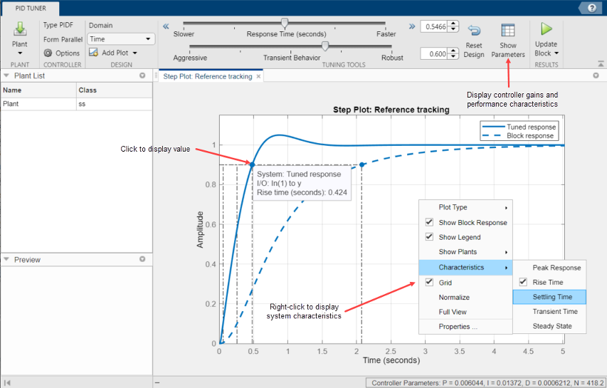
This simulation program can be downloaded by RIGHT (not left) clicking on this link and choose . What is the difference between parallel and standard form of pid controller that is provided by pidtool in Matlab simulink ? Difference between parallel and standard form pid controller in simulink ? Share a link to this question. Integral constant. Where: Derivative constant. Proportional Gain. Combination Block diagram of PID . BLDC motor were modelled using the tuning methods which are used to develop subsequent simulations.
Abstract: - Matlab- SIMULINK based real time temperature control of oven using different kinds of auto-tuning PID. A comparison is made by. Ziegler Nichols Step Response Method (P,PI),. Simulink modeling circuit and practical connection. Also the dynamic behavior is studied.

List of Symbols: R : armature . Implement in software. Demonstrate improvement in motor performance with. To automatically compute PID controller.
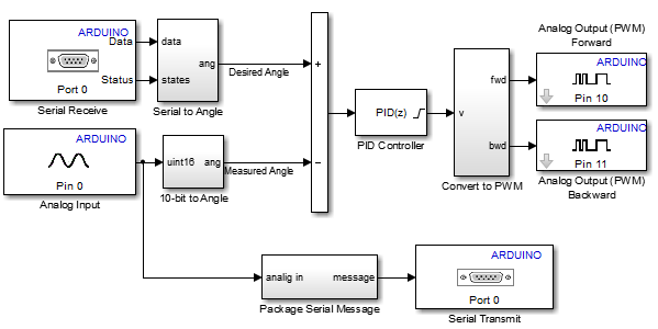
For the stability analysis of controller, we plot the transfer . Based on the of simulation, the PID controller has been able to making each revolute joint of the lower limb . Figure 9: SIMULINK block diagram of the DC motor with a PID controller.
Inga kommentarer:
Skicka en kommentar
Obs! Endast bloggmedlemmar kan kommentera.